
Product Description
Symbols E. and W.
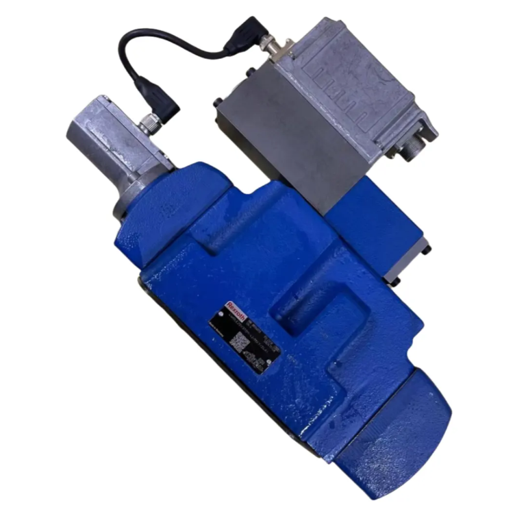
The Model 4WRLE valve is a pilot-operated directional control valve with electrical position feedback and integrated electronics (OBE).
Configuration
The basic construction of the valve consists of 3 main components:
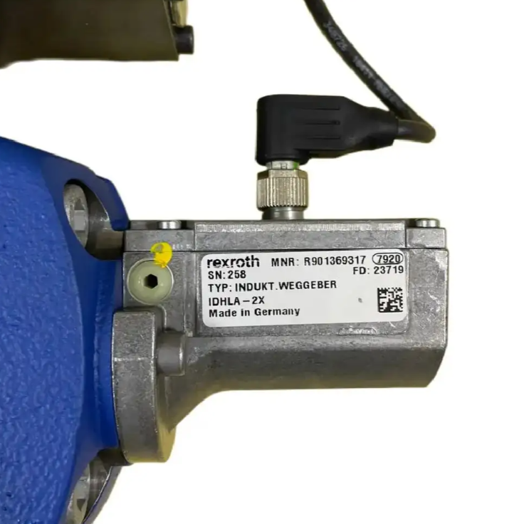
Pilot-operated control valve with control spool and sleeve, return spring, control coil and inductive position sensor (with optional electronics protection film) and attenuator plate
Main valve with centering spring and position feedback
Integrated electronics (OBE) with analog or IO-Link interface
Functions
When the integrated control electronics (OBE) are switched off or inactive, the control spool of the pilot control valve is spring-loaded in the “fail-safe” position. The control spool of the main valve is in its spring centered position.
The integrated control electronics (OBE) compares the constant control value with the actual value of the main valve spool position. In case of a control deviation, the control coil is activated. Due to the change in magnetic force, the pilot control spool will be adjusted against the spring.
The flow activated by the control profile causes an adjustment of the main control spool. The travel/control profile of the main control spool is adjusted in proportion to the control value.
Pilot oil can be supplied to the pilot control valve internally via port P or externally via port X.
Rexroth 4WRLE25V370M-4X/MXY/24A1 Proportional Controller Model Explanation Explanation:
1. 4WRL = Pilot Operated Directional Control Valve with Electrical Position Feedback and Integrated Electronics (OBE) 4WRL Series No., Fixed
2.25=NG25 size 25 16=NG16 size 16 27=NG27 size 27
3.V=symbol/circuit diagram “control slide valve symbol
4.370 = 370 l/min, rated flow (Δp = 5 bar/control side)
5.M=Flow characteristic, progressive, with linear control (symbol Q3-)
6.4X = Component series 40 -49 (40 -49: mounting and connection dimensions unchanged) X indicates any number from 0 to 9
7.M = NBR seals, suitable for mineral oils (HL, HLP) according to DIN 51524
8.XY=Pilot oil flow, pilot oil supply, external pilot oil return PY=Internal pilot oil, external pilot oil return PT=Internal pilot oil supply; internal pilot oil return XT=Pilot oil supply, internal pilot oil return
9.24=Supply voltage 24V
10.A1=Interface for control electronics, command value input ±10V F1=Command value input 4-20 mA L1=LO-link interface C6=Command value ±10 mA, actual value 4.20 mA, release (connector 6+PE)
Control coil de-energized
In the following error condition, the integrated electronics (OBE) de-energizes the control coil, the pilot control spool will be set to the “Fail Safe” position and the pilot chamber of the main valve will be unloaded. By spring operation, the main valve control spool will move to the center position.
Below low supply voltage
only at connection “F1
Below the small current control value 2 mA (including cable interruption of the control value line (current loop)). -
Only at interface “L1”
Enable not activated, communication interrupted -
In the event of an internal IO-Link failure -
only at interface “C6
additional enable not activated -
Attenuation board “D”
The attenuation board reduces the acceleration amplitude (frequency >300 Hz) on the integrated electronics.


