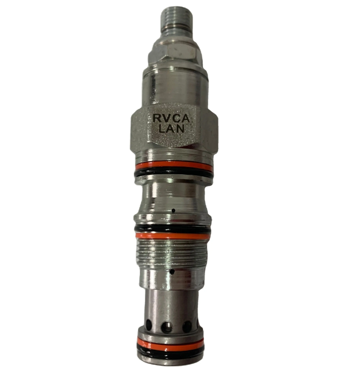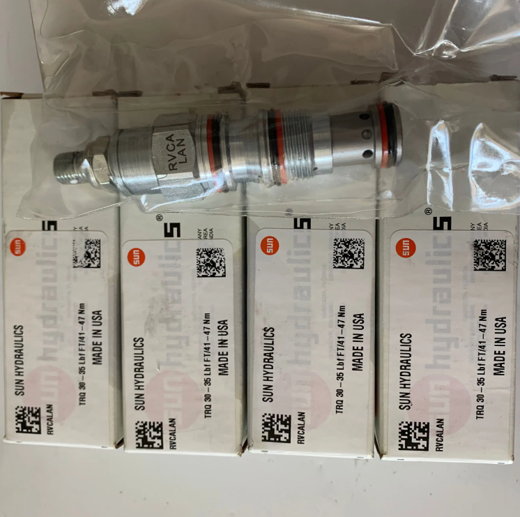

| Cavity | T-11A |
| Series | 1 |
| Capacity | 15 gpm |
| Maximum Operating Pressure | 5000 psi |
| Factory Pressure Settings Established at | 4 gpm |
| Control Pilot Flow | 7 - 10 in³/min. |
| Maximum Valve Leakage at 110 SUS (24 cSt) | 2 in³/min.@1000 psi |
| Response Time - Typical | 10 ms |
| Adjustment - No. of CW Turns from Min. to Max. setting | 5 |
| Valve Hex Size | 7/8 in. |
| Valve Installation Torque | 30 - 35 lbf ft |
| Adjustment Screw Internal Hex Size | 5/32 in. |
| Locknut Hex Size | 9/16 in. |
| Locknut Torque | 80 - 90 lbf in. |
External interface control, pilot control type, balanced slide valve structure relief valve is normally closed pressure regulating valve. When the inlet (port 1) pressure reaches the valve setting, the valve begins to overflow to the tank (port 2), throttling to regulate pressure. This type of valve provides an external interface (port 3) between the main stage piston and the pilot stage, which can be connected to other pilot stage control valves or 2-way valves to realize remote control. These valves provide high pressure regulation accuracy, low pressure fluctuation with flow rate, smooth regulation, low noise, and moderate response speed.
A remote pilot relief valve at port 3 (external connection) can control this valve below set pressure.
Accepts high pressure at port 2; suitable for use in cross-ported relief lines. Consider slide valve leakage if applying to cross-ported relief lines.
Damping holes in the main stage are protected by a 150 micron stainless steel screen. External Port Control Balancing Slide Valve Relief Valve
Not suitable for use in load locking applications because of slide valve leakage.
The back pressure at the tank port (port 2) is increased directly to the valve setting in a 1:1 ratio.
Cartridge valves configured with EPDM seals can be used in phosphate ester hydraulic fluid systems. Exposure to petroleum-based hydraulic fluids or lubricating greases can damage the seals.


